FREQUENCY
0.7–2.5 GHz
TYP. PEAK GAIN
3.5 dBi
TYP. VSWR
≤ 2.5:1
POLARIZATION
Linear
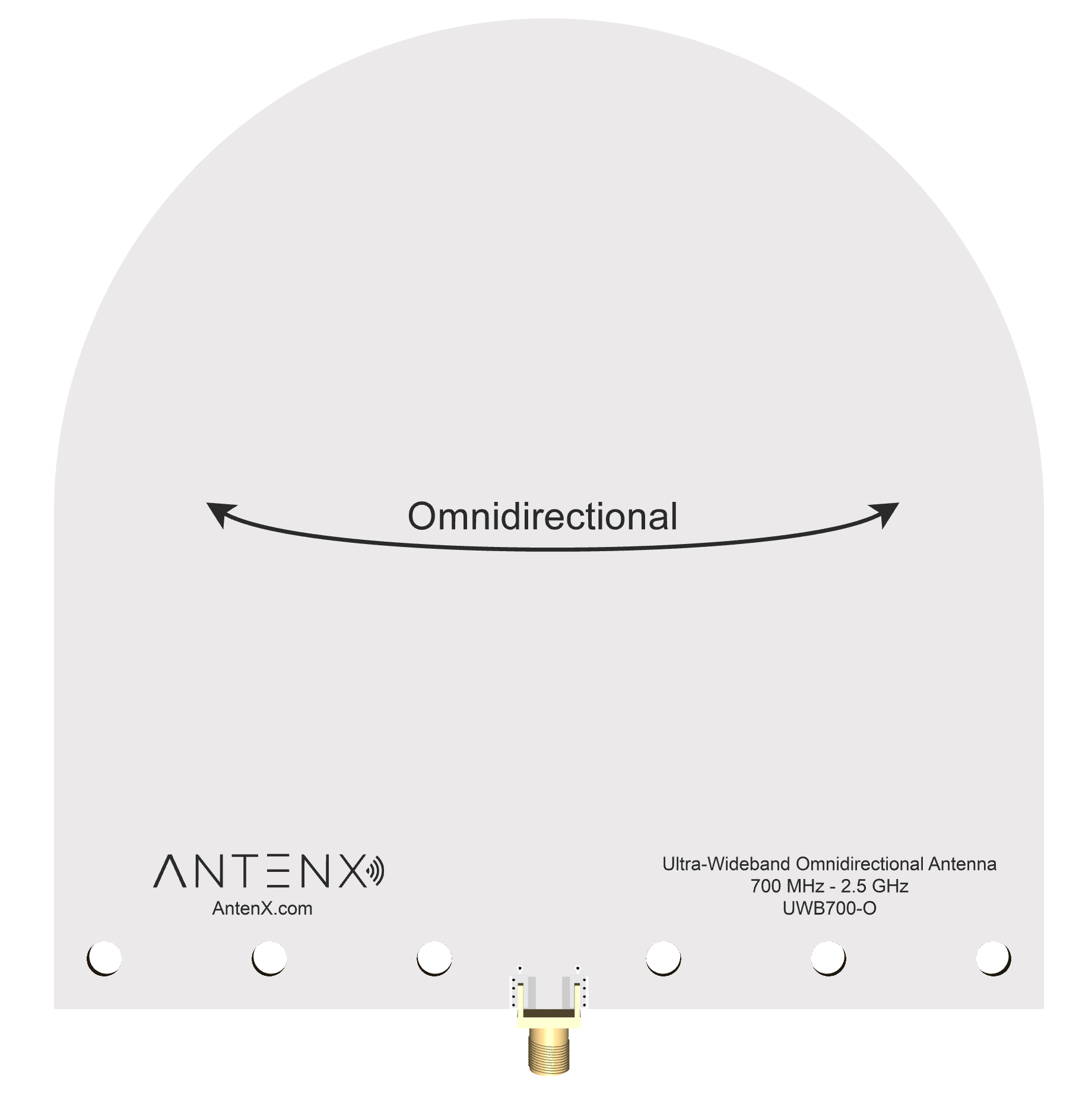
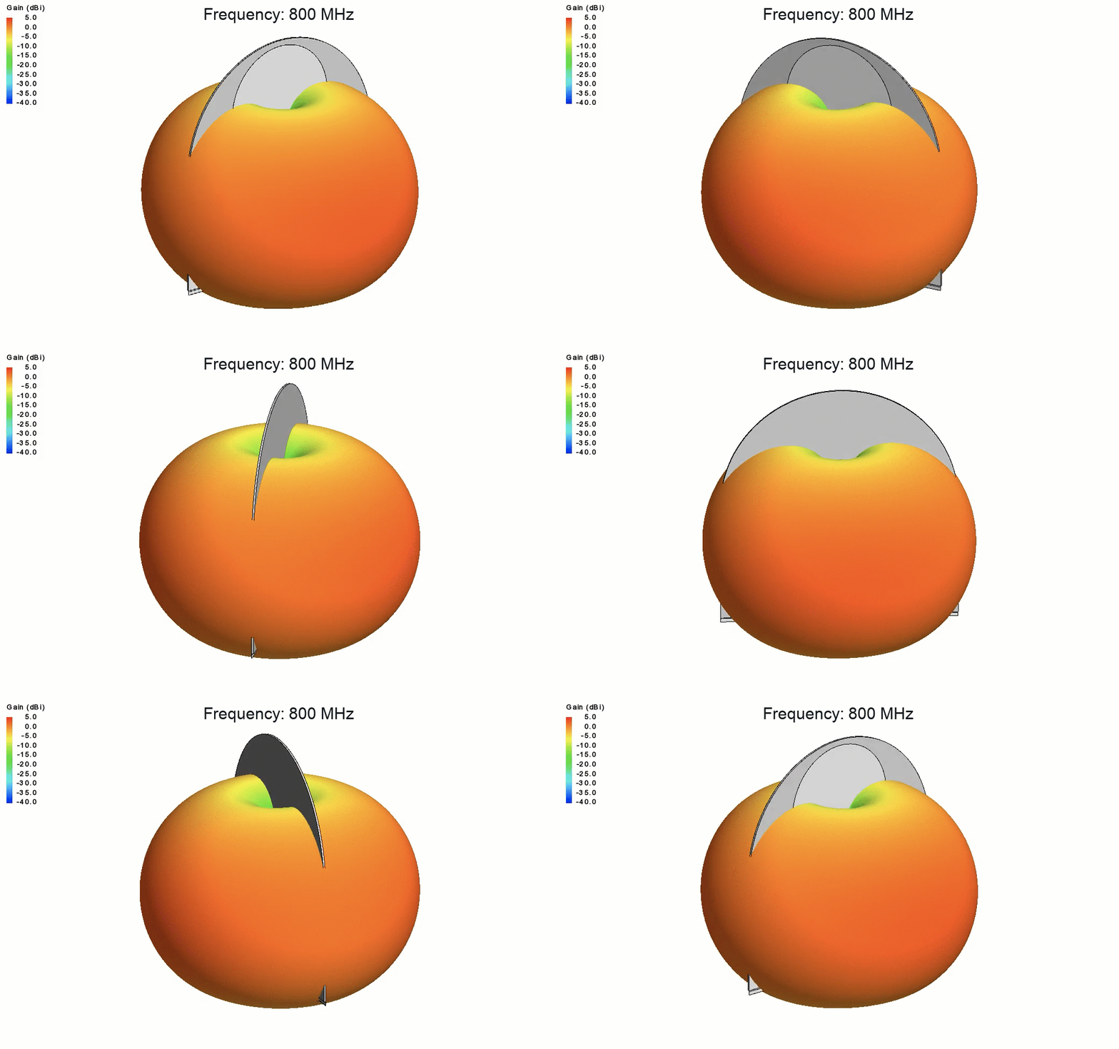
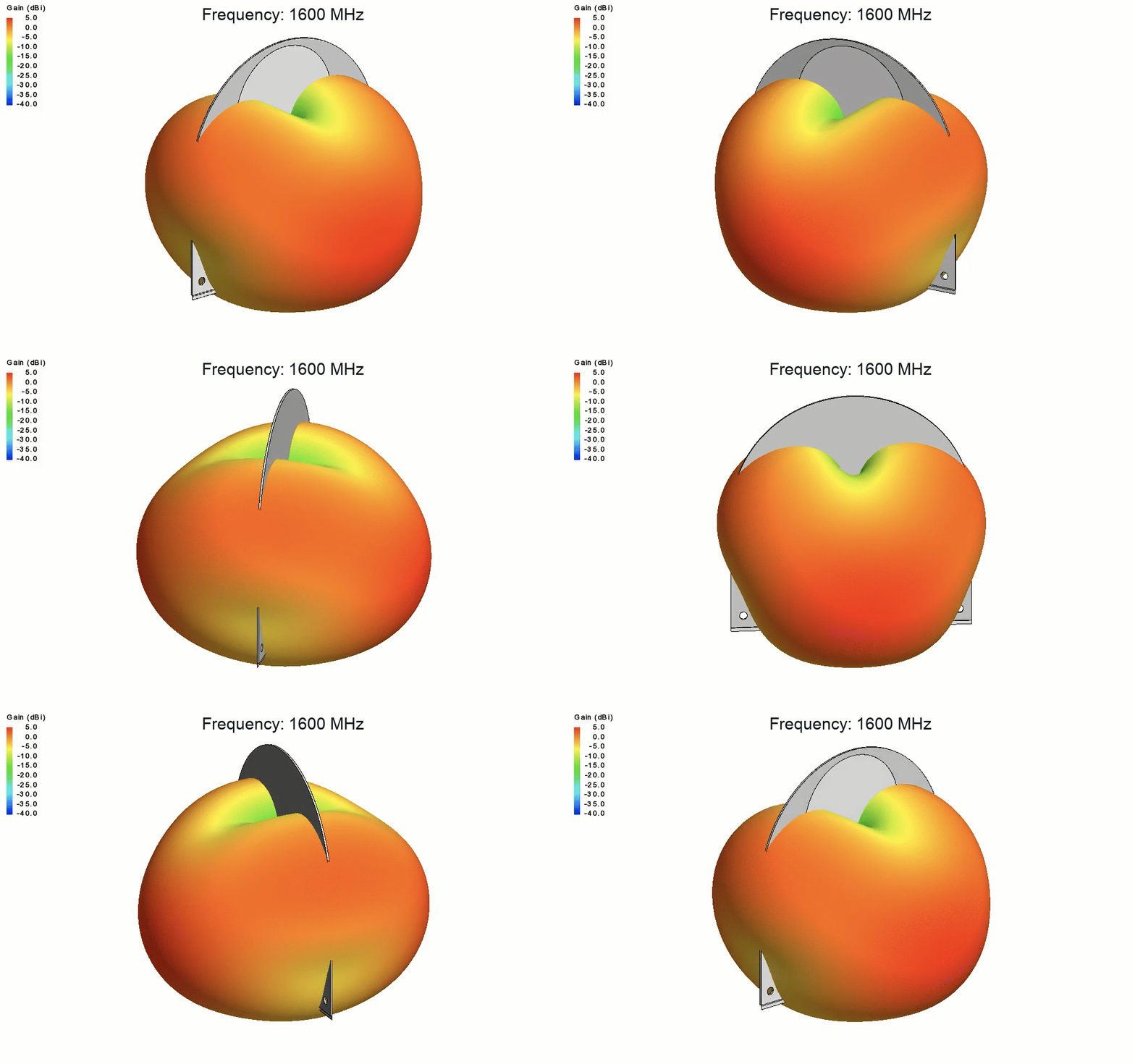
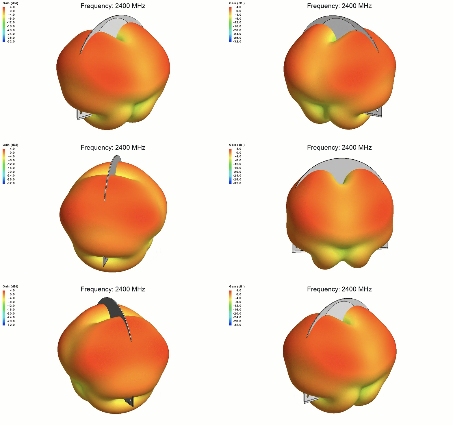
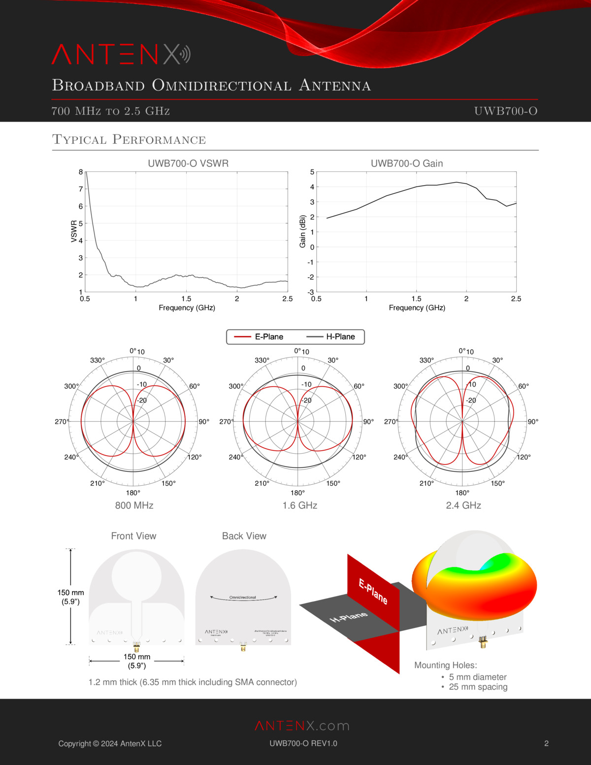
Omnidirectional coverage
360° azimuth pattern across the full band.
Thin & lightweight
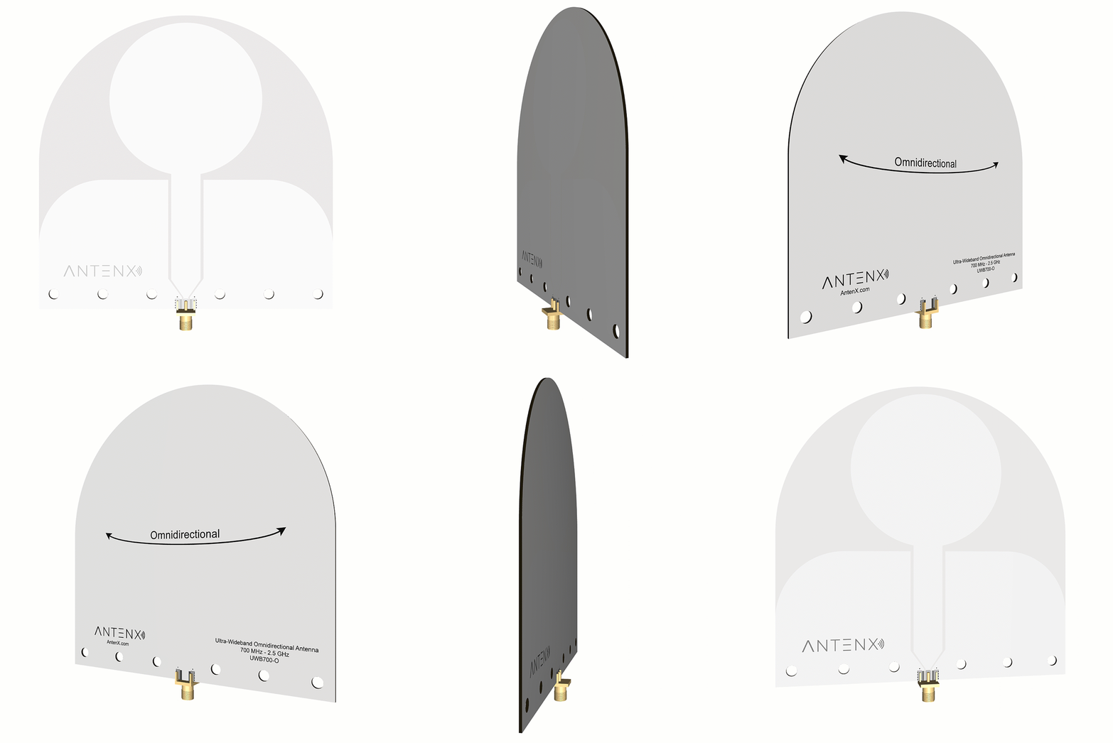
FR-4 board, 5.9 × 5.9 in and under 0.25 in thick.
Designed in the USA
Designed, assembled, and tested in California.
Product Details
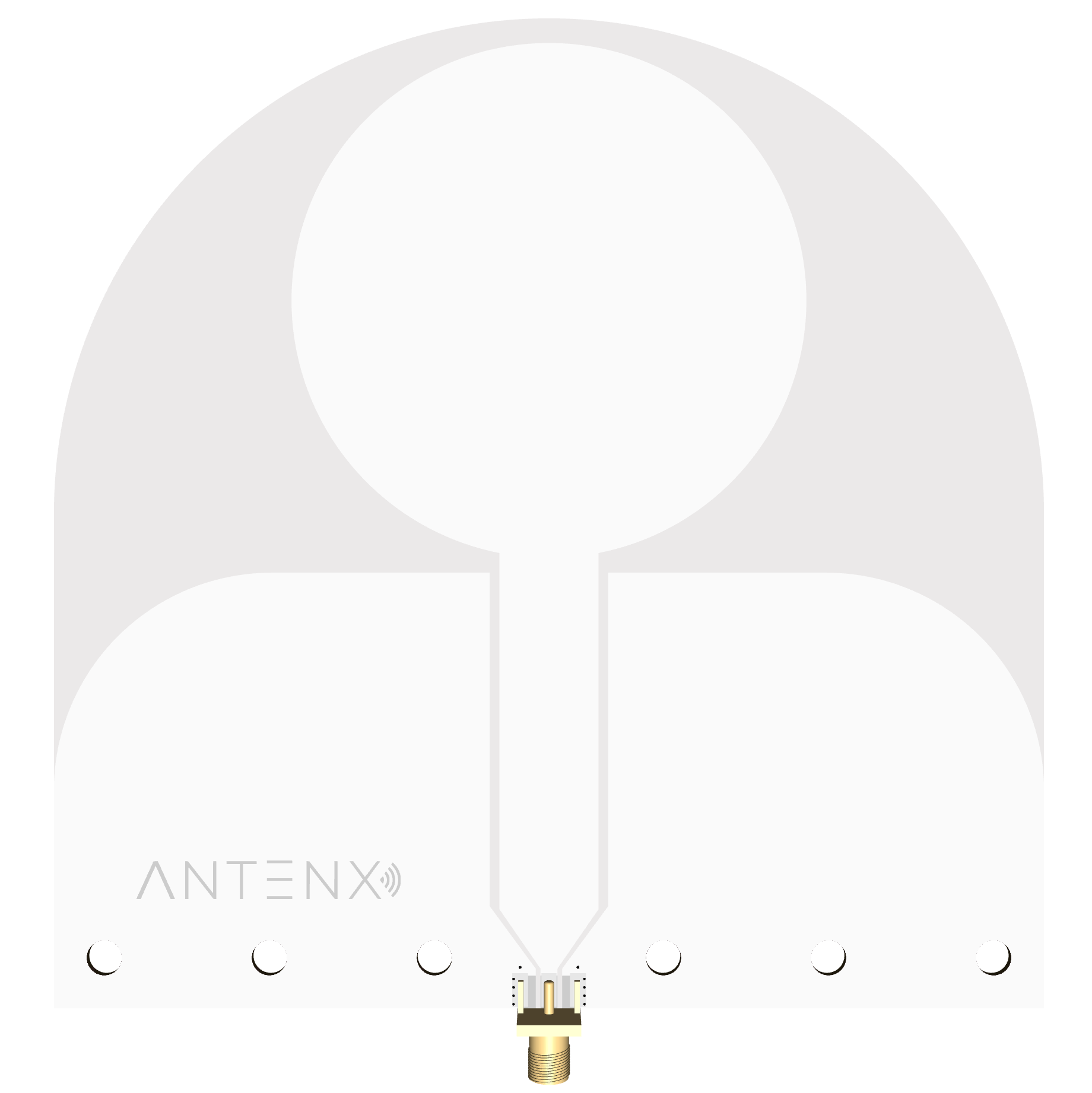
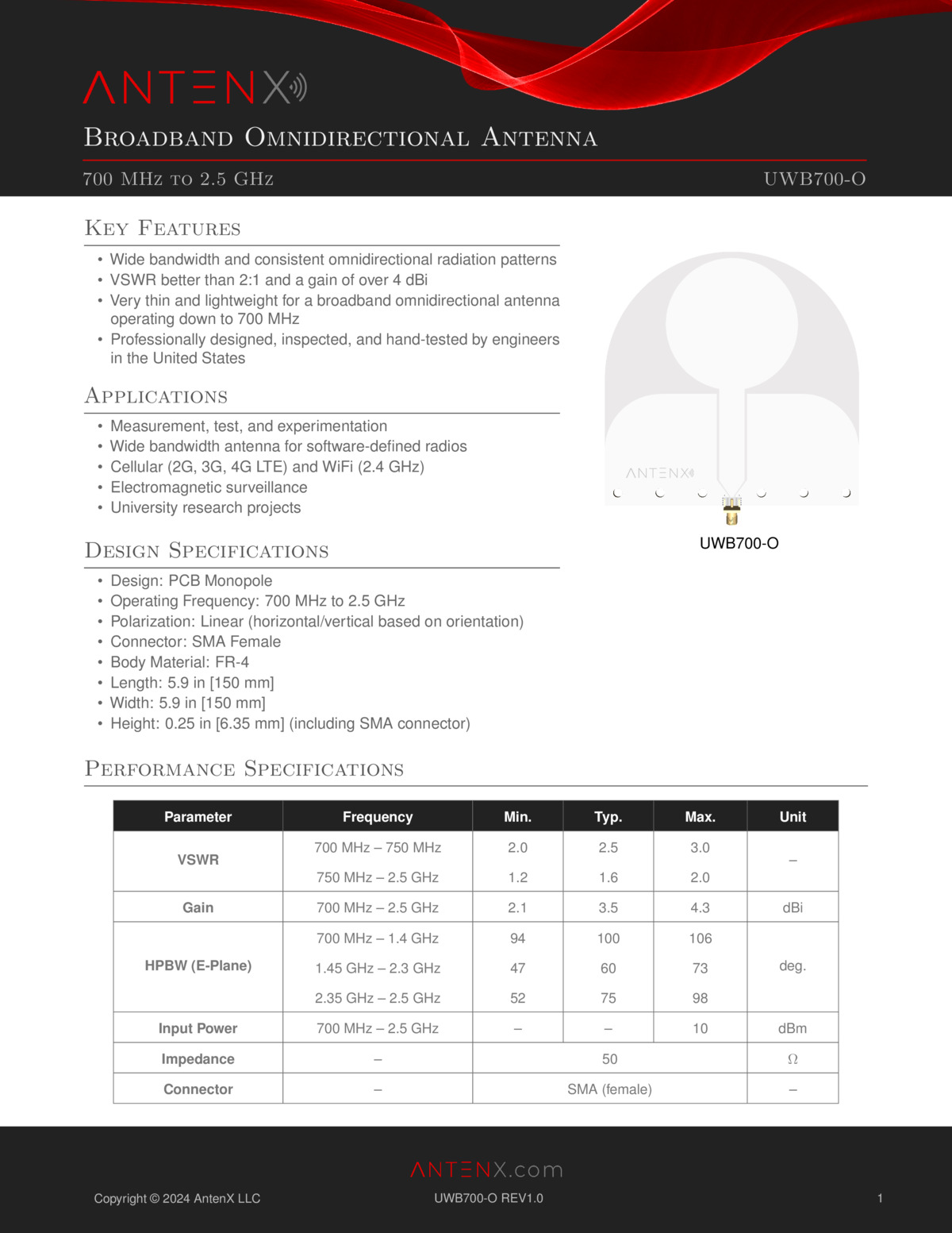
The UWB700-O is a broadband PCB monopole antenna covering 700 MHz to 2.5 GHz with an omnidirectional azimuth radiation pattern and typical gain of 3.5 dBi. Its thin, lightweight FR-4 board (under a quarter-inch thick) makes it an easy, low-cost way to add wideband 360-degree coverage to a test bench, mast, or enclosure. It is well suited to software-defined radio, signal monitoring, electromagnetic surveillance, and university research.
- Broadband PCB monopole with an omnidirectional (360° azimuth) radiation pattern across 700 MHz to 2.5 GHz.
- Typical gain of 3.5 dBi; VSWR typically below 2.5:1.
- Thin, lightweight FR-4 board (5.9 × 5.9 in, under 0.25 in thick including the SMA connector).
- Linearly polarized, 50 Ω, SMA female, ideal for SDR, monitoring, and surveillance.
- Versatile across SDR, electromagnetic surveillance, cellular / WiFi / LoRa / IoT, and university research.
- Typical performance data (.txt) available for download.
Specifications
General
| Design | PCB monopole (omnidirectional) |
| Polarization | Linear (H/V by orientation) |
| Connector | SMA female |
| Impedance | 50 Ω |
| Maximum input power | 10 dBm (10 mW) |
| Construction | FR-4 printed circuit board |
| Mounting | 5 mm holes, 25 mm spacing |
| Dimensions (L × W × H) | 150 × 150 × 6.35 mm (5.9 × 5.9 × 0.25 in) |
Performance over frequency
| PARAMETER | FREQUENCY | MIN | TYP | MAX | UNIT |
|---|---|---|---|---|---|
| VSWR | 0.70 – 0.75 GHz | 2.0 | 2.5 | 3.0 | – |
| 0.75 – 2.5 GHz | 1.2 | 1.6 | 2.0 | ||
| Gain | 0.7 – 2.5 GHz | 2.1 | 3.5 | 4.3 | dBi |
| HPBW, E-plane | 0.70 – 1.4 GHz | 94 | 100 | 106 | deg |
| 1.45 – 2.3 GHz | 47 | 60 | 73 | ||
| 2.35 – 2.5 GHz | 52 | 75 | 98 |
Specifications are typical and subject to change without notice. The H-plane (azimuth) pattern is omnidirectional; HPBW is specified in the E-plane (elevation). Height includes the SMA connector (board is 1.2 mm thick).